Universal joint

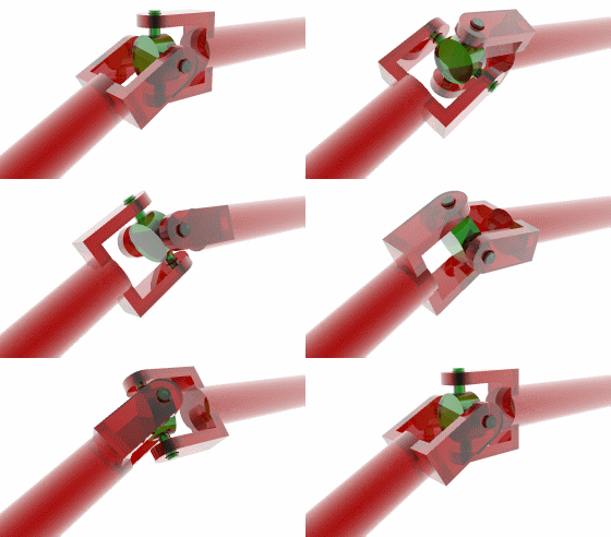
A universal bersama, U sendi, Cardan bersama, Hardy-Spicer sendi, atau sendi Hooke adalah bersama dalam sebuah batang kaku yang memungkinkan batang 'membungkuk' dalam segala arah, dan umumnya digunakan dalam rotary shaft yang mengirimkan gerakan. It consists of a pair of hinges located close together, oriented at 90° to each other, connected by a cross shaft. Terdiri dari sepasang engsel terletak berdekatan, berorientasi pada 90 ° untuk satu sama lain, dihubungkan dengan poros salib.
Sejarah
The main concept of the universal joint is based on the design of gimbals , which have been in use since antiquity. Konsep utama sendi universal didasarkan pada desain gimbals, yang telah digunakan sejak jaman dahulu. One anticipation of the universal joint was its use by the Ancient Greeks on ballistae . Salah satu antisipasi bersama yang universal itu yang digunakan oleh orang Yunani Kuno pada busur. The first person known to have suggested its use for transmitting motive power was Gerolamo Cardano , an Italian mathematician, in 1545, although it is unclear whether he produced a working model. Christopher Polhem later reinvented it and it was called "Polhem knot". Orang pertama yang diketahui telah mengusulkan penggunaannya untuk transmisi motif kekuasaan Gerolamo Cardano, seorang matematikawan Italia, tahun 1545, meskipun tidak jelas apakah ia mengeluarkan sebuah model kerja. Christopher Polhem kemudian diciptakan kembali dan itu disebut "Polhem simpul". In Europe, the device is often called the Cardan joint or Cardan shaft . Robert Hooke produced a working universal joint in 1676, giving rise to an alternative name, the Hooke's joint . Di Eropa, perangkat ini sering disebut sendi atau Cardan shaft Cardan. Robert Hooke menghasilkan universal yang bekerja bersama di 1676, sehingga menimbulkan nama alternatif, yang Hooke bersama. Though the first use of the name universal joint is sometimes attributed to American car manufacturer Henry Ford , the term appeared in patent documents as early as 1884 when Charles H. Amidon was awarded United States Letters Patent No. 298,542 for a bit brace. Meskipun penggunaan pertama dari nama sendi universal kadang-kadang dikaitkan dengan produsen mobil Amerika Henry Ford, istilah muncul di dokumen paten sejak 1884 ketika Charles H. Amidon dianugerahi Amerika Serikat Letters Patent No 298.542 untuk sedikit penjepit.Persamaan gerak

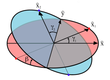
Diagram of variables for the universal joint. Diagram variabel untuk bersama universal. Axle 1 is perpendicular to the red plane and axle 2 is perpendicular to the blue plane at all times. Poros 1 adalah tegak lurus terhadap pesawat merah dan poros 2 adalah tegak lurus terhadap pesawat biru sepanjang waktu. These planes are at an angle β with respect to each other. Pesawat ini adalah pada sudut β terhadap satu sama lain. The angular displacement (rotational position) of each axle is given by γ 1 and γ 2 respectively, which are the angles of the unit vectors Perpindahan sudut (rotasi posisi) dari masing-masing poros diberikan oleh 1 dan γ γ 2 masing-masing, yang merupakan unit sudut vektor  and dan
  with respect to their initial positions along the x and y axes. sehubungan dengan posisi awal mereka di sepanjang sumbu x dan y. The Itu
  and dan
  vectors are fixed by the gimbal connecting the two axles and so are constrained to remain perpendicular to each other at all times. vektor yang ditetapkan oleh gimbal menghubungkan dua as dan begitu juga dibatasi untuk tetap tegak lurus satu sama lain sepanjang waktu.
 and dan
  with respect to their initial positions along the x and y axes. sehubungan dengan posisi awal mereka di sepanjang sumbu x dan y. The Itu
  and dan
  vectors are fixed by the gimbal connecting the two axles and so are constrained to remain perpendicular to each other at all times. vektor yang ditetapkan oleh gimbal menghubungkan dua as dan begitu juga dibatasi untuk tetap tegak lurus satu sama lain sepanjang waktu.
 - γ 1 The angle of rotation for axle 1 1 γ Sudut rotasi untuk poros 1
- γ 2 The angle of rotation for axle 2 γ 2 sudut rotasi untuk as roda 2
- β The bend angle of the joint, or angle of the axles with respect to each other, with zero being parallel or straight through. β sudut yang membengkokkan sendi, atau sudut as dengan menghormati satu sama lain, dengan nol yang sejajar atau lurus lewat.
 and dan
  and the planes of rotation of each axle. dan rotasi pesawat dari masing-masing poros. These planes of rotation are perpendicular to the axes of rotation and do not move as the axles rotate. Rotasi pesawat ini adalah tegak lurus terhadap sumbu rotasi dan tidak bergerak sebagai as roda berputar. The two axles are joined by a gimbal which is not shown. Kedua as roda dihubungkan oleh gimbal yang tidak ditampilkan. However, axle 1 attaches to the gimbal at the red points on the red plane of rotation in the diagram, and axle 2 attaches at the blue points on the blue plane. Namun, poros 1 menempel ke gimbal di titik-titik merah pada rotasi pesawat merah dalam diagram, dan as roda 2 menempel di titik-titik biru di pesawat biru. Coordinate systems fixed with respect to the rotating axles are defined as having their x-axis unit vectors ( Sistem koordinat tetap sehubungan dengan as roda yang berputar didefinisikan sebagai mereka mempunyai sumbu x unit vektor (
  and dan
  ) pointing from the origin towards one of the connection points. ) Menunjuk dari titik asal menuju salah satu titik sambungan. As shown in the diagram, Seperti ditunjukkan dalam diagram,
  is at angle γ 1 with respect to its beginning position along the x axis and adalah pada sudut γ 1 dengan hormat ke posisi awal sepanjang sumbu x dan
  is at angle γ 2 with respect to its beginning position along the y axis. adalah pada sudut γ 2 dengan hormat ke posisi awal sepanjang sumbu-y.
 is confined to the "red plane" in the diagram and is related to γ 1 by: adalah terbatas pada "pesawat merah" dalam diagram dan terkait dengan γ 1 oleh:
 is confined to the "blue plane" in the diagram and is the result of the unit vector on the x axis adalah terbatas pada "pesawat biru" dalam diagram dan merupakan hasil dari vektor satuan pada sumbu x
 ![\ hat (x) = [1,0,0]](http://upload.wikimedia.org/math/3/b/a/3bac86090d30cc463a12cd3c20dbb933.png) being rotated through Euler angles sedang diputar melalui sudut Euler
being rotated through Euler angles sedang diputar melalui sudut Euler  ]: ]
]: ] and dan
  vectors is that since they are fixed in the gimbal, they must remain at right angles to each other: vektor adalah bahwa karena mereka adalah tetap di gimbal, mereka harus tetap tegak lurus satu sama lain:
Double Cardan Shaft
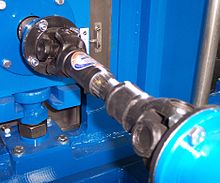
A configuration known as a double Cardan joint drive shaft partially overcomes the problem of jerky rotation. Sebuah konfigurasi dikenal sebagai Cardan ganda bersama sebagian poros kardan mengatasi masalah tersentak-sentak rotasi. This configuration uses two U-joints joined by an intermediate shaft, with the second U-joint phased in relation to the first U-joint to cancel the changing angular velocity. Konfigurasi ini menggunakan dua U-sendi bergabung oleh poros perantara, dengan U-sendi kedua bertahap dalam hubungannya dengan U-sendi pertama untuk membatalkan perubahan kecepatan sudut. In this configuration, the assembly will result in an almost constant velocity, provided both the driving and the driven shaft are parallel and the two universal joints are correctly aligned with each other - usually Dalam konfigurasi ini, dewan akan menghasilkan kecepatan yang hampir konstan, baik yang disediakan mengemudi dan digerakkan poros yang sejajar dan dua universal joint yang benar selaras dengan satu sama lain - biasanya 90°. 90 °. This assembly is commonly employed in rear wheel drive vehicles, where it is known as a drive shaft or propeller (prop) shaft. Majelis ini umumnya bekerja di roda belakang kendaraan, di mana ia dikenal sebagai poros kardan atau baling-baling (prop) poros.
Even when the driving and driven shafts are parallel, if Bahkan ketika mengemudi dan digerakkan poros sejajar, jika
Double Cardan Bersama
Main article: Constant-velocity joint#Double Cardan Artikel utama: kecepatan konstan-sendi # Double Cardan
A double cardan joint consists of two universal joints mounted back to back, with no intermediate shaft. Bersama cardan ganda terdiri dari dua universal joint dipasang kembali ke belakang, tanpa perantara poros. The second UJ cancels the velocity errors introduced by the single joint, and so they act as a CV joint. UJ kedua membatalkan kesalahan kecepatan diperkenalkan oleh satu sendi, dan sehingga mereka bertindak sebagai gabungan CV.Thompson Coupling
Main article: Constant-velocity joint#Thompson coupling Artikel utama: kecepatan konstan-sendi # Thompson coupling
A Thompson Coupling is a refined version of the double Cardan joint. Sebuah Thompson Coupling adalah versi halus Cardan ganda bersama. It offers slightly increased efficiency with the penalty of some increase in complexity. Menawarkan sedikit peningkatan efisiensi dengan hukuman beberapa peningkatan kompleksitas.
![\ hat (\ mathbf (x)) _1 = [\ cos \ gamma_1 \,, \, \ sin \ gamma_1 \,, \, 0]](http://upload.wikimedia.org/math/a/c/a/aca5995a132783341b0dba0c2b09435c.png)
![\ hat (\ mathbf (x)) _2 = [- \ cos \ beta \ sin \ gamma_2 \,, \, \ cos \ gamma_2 \,, \, \ sin \ beta \ sin \ gamma_2]](http://upload.wikimedia.org/math/8/c/a/8ca0854ee6f68be4fc2accf3b48142c9.png)


Tidak ada komentar:
Posting Komentar